
Dragonflow Deep Dive (Part 2)
11 May 2015If you havent read part 1 of this deep dive introduction, make sure to read it here.
In the previous part we have seen how Dragonflow installs its default pipeline and we then created two networks (network 1 with subnet 10.1.0.0/24 and network 2 with subnet 10.2.0.0/24) and connected them with a router.
All the flows were configured in a proactive mode, as soon as Dragonflow noticed configuration change in Neutron.
Lets recall of the current status of br-int flow table
 cookie=0x0, duration=260870.502s, table=0, n_packets=19, n_bytes=1394, priority=1 actions=goto_table:40
 cookie=0x0, duration=265383.764s, table=0, n_packets=0, n_bytes=0, priority=0 actions=NORMAL
 cookie=0x0, duration=260870.502s, table=0, n_packets=0, n_bytes=0, priority=1000,in_port=8 actions=NORMAL
 cookie=0x0, duration=260870.502s, table=0, n_packets=0, n_bytes=0, priority=1000,in_port=7 actions=NORMAL
 cookie=0x0, duration=260870.502s, table=0, n_packets=0, n_bytes=0, priority=1000,in_port=6 actions=NORMAL
 cookie=0x0, duration=260870.502s, table=0, n_packets=0, n_bytes=0, priority=1000,in_port=2 actions=NORMAL
 cookie=0x0, duration=265389.736s, table=23, n_packets=0, n_bytes=0, priority=0 actions=drop
 cookie=0x0, duration=260870.502s, table=40, n_packets=26, n_bytes=2076, priority=10,dl_dst=01:00:00:00:00:00/01:00:00:00:00:00 actions=NORMAL
 cookie=0x0, duration=260870.502s, table=40, n_packets=0, n_bytes=0, priority=1 actions=goto_table:52
 cookie=0x0, duration=260870.502s, table=40, n_packets=0, n_bytes=0, priority=100,dl_dst=ff:ff:ff:ff:ff:ff actions=NORMAL
 cookie=0x0, duration=260870.502s, table=40, n_packets=6, n_bytes=252, priority=1000,arp actions=goto_table:51
 cookie=0x0, duration=260870.502s, table=51, n_packets=6, n_bytes=252, priority=1 actions=NORMAL
 cookie=0x0, duration=260870.501s, table=51, n_packets=0, n_bytes=0, send_flow_rem priority=100,arp,metadata=0x1f42,arp_tpa=10.1.0.1,arp_op=1 actions=set_field:2->arp_op,move:NXM_NX_ARP_SHA[]->NXM_NX_ARP_THA[],move:NXM_OF_ARP_SPA[]->NXM_OF_ARP_TPA[],set_field:fa:16:3e:c0:8d:8b->eth_src,set_field:fa:16:3e:c0:8d:8b->arp_sha,set_field:10.1.0.1->arp_spa,IN_PORT
 cookie=0x0, duration=260870.502s, table=51, n_packets=0, n_bytes=0, send_flow_rem priority=100,arp,metadata=0x1f43,arp_tpa=10.2.0.1,arp_op=1 actions=set_field:2->arp_op,move:NXM_NX_ARP_SHA[]->NXM_NX_ARP_THA[],move:NXM_OF_ARP_SPA[]->NXM_OF_ARP_TPA[],set_field:fa:16:3e:c5:02:4d->eth_src,set_field:fa:16:3e:c5:02:4d->arp_sha,set_field:10.2.0.1->arp_spa,IN_PORT
 cookie=0x0, duration=260870.502s, table=52, n_packets=0, n_bytes=0, priority=1 actions=goto_table:53
 cookie=0x0, duration=260870.502s, table=52, n_packets=0, n_bytes=0, priority=20,ip,metadata=0x1f43,nw_dst=10.1.0.0/24 actions=CONTROLLER:65535
 cookie=0x0, duration=260871.344s, table=52, n_packets=0, n_bytes=0, priority=20,ip,metadata=0,nw_dst=10.1.0.0/24 actions=CONTROLLER:65535
 cookie=0x0, duration=260870.500s, table=52, n_packets=0, n_bytes=0, priority=30,ip,metadata=0x1f42,nw_dst=10.1.0.0/24 actions=NORMAL
 cookie=0x0, duration=260870.502s, table=52, n_packets=0, n_bytes=0, priority=20,ip,metadata=0x1f42,nw_dst=10.2.0.0/24 actions=CONTROLLER:65535
 cookie=0x0, duration=260870.502s, table=52, n_packets=0, n_bytes=0, priority=30,ip,metadata=0x1f43,nw_dst=10.2.0.0/24 actions=NORMAL
 cookie=0x0, duration=265389.665s, table=60, n_packets=0, n_bytes=0, priority=1 actions=move:NXM_NX_TUN_ID[0..31]->NXM_NX_PKT_MARK[],output:6
Now, lets launch two VM’s one at each network and see how this table changes, the following diagram show you the topology view after we added the VM
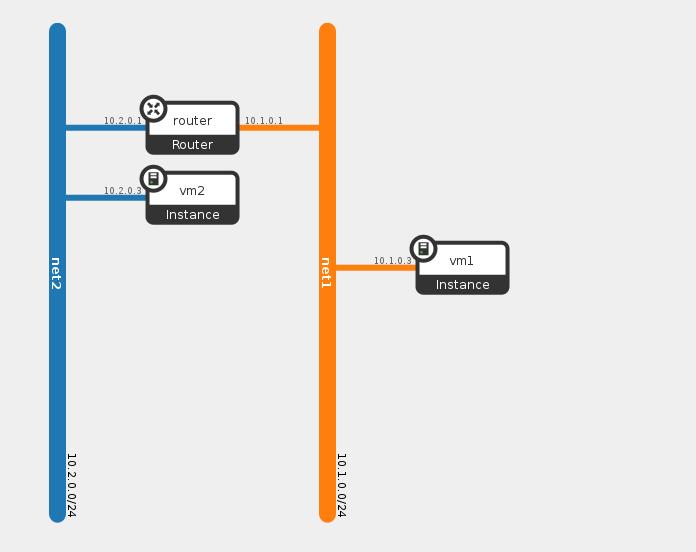
We can see VM1 connected to network1 with IP 10.1.0.3 and VM2 connected to network2 with IP 10.2.0.3
Lets see how this change affected the flow table, for convenience i only paste here the new added flows, all the rest of the flows remains the same
 1.cookie=0x0, duration=153.339s, table=0, n_packets=27, n_bytes=2462, priority=1000,in_port=11 actions=write_metadata:0x1f42/0xffff,goto_table:40
 2.cookie=0x0, duration=149.796s, table=0, n_packets=23, n_bytes=2182, priority=1000,in_port=12 actions=write_metadata:0x1f43/0xffff,goto_table:40
We can see that two flows were added which matches on the local openvswitch ports and as action write a specific metadata and send the traffic to the classifier table (table 40).
In Dragonflow we configure this kind of flow for every VM that is launched on the compute node and matches on its assigned local openvswitch port, the purpose of this flow is to classify the network this VM belongs to. We achieve this by writing the network segmentation id as the metadata field, we use this later in the pipeline to classify the traffic type (L2, L3, which tunnel to output).
In the above example we can see two new flows, one for each VM and as you can see each one has a different metadata field representing they are from different networks.
Now lets try to ping from VM2 (10.2.0.3) to VM1 (10.1.0.3) and see what happens.
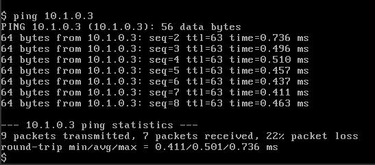
We can see that the first ping latency is abit bigger than the rest, this is because the first packet is matched and sent to the controller, the controller checks the route validity (if there is a route between the two VM’s) and then configure two flows which represent the two sides of the connection.
Before looking at the newly configured flows by the controller, lets understand how the packet is first matched and sent to the controller.
The packet first arrives to table ‘0’, there it is matched by the input port to the flows we described above and the networking segmentation id is written to its metadata field.
The first packet is matched as an ARP request (for the default gateway IP) and it is being sent to table 51, in table 51 an ARP responder match for the specific network (by the IP and segmentation id) and sends an ARP reply with the router interface MAC (the default gateway).
We saw the ARP responder flows installations when we connected the network to a router in the previous post.
The next packet also gets the network segmentation written to it, but now it is being sent to table 52 from our classifier table (not an ARP). Table 52 is the L3 distributed router implementation, if you remember from the previous post Dragonflow install flows which matches every subnet to subnet pairs and sends the traffic to the controller (you can view them in the top flows capture in this post).
Its important to remember here that we use the segmentation id (written to the metadata) and the destination IP to understand if this is a L2 or L3 traffic (Dragonflow currently sends L2 traffic to NORMAL pipeline). As we also previously saw, the flows in this table must match any possible east-west traffic, we do this in order to classify which traffic is east-west and which is north-south.
If we now look at the configured flows, we can see two new flows
 cookie=0x1008000000019, duration=5.704s, table=52, n_packets=1, n_bytes=98, idle_timeout=300, priority=100,ip,metadata=0x1f43,in_port=12,dl_src=fa:16:3e:cf:4b:ed,dl_dst=fa:16:3e:c5:02:4d,nw_src=10.2.0.3,nw_dst=10.1.0.3 actions=dec_ttl,set_field:fa:16:3e:c5:02:4d->eth_src,set_field:fa:16:3e:00:17:e6->eth_dst,output:11
 cookie=0x1008000040051, duration=5.708s, table=52, n_packets=1, n_bytes=98, idle_timeout=300, priority=100,ip,metadata=0x1f42,in_port=11,dl_src=fa:16:3e:00:17:e6,dl_dst=fa:16:3e:c0:8d:8b,nw_src=10.1.0.3,nw_dst=10.2.0.3 actions=dec_ttl,set_field:fa:16:3e:c0:8d:8b->eth_src,set_field:fa:16:3e:cf:4b:ed->eth_dst,output:12
These two flows are representing the two directions of the connection between the two VM’s by matching the source and destination, the action replaces the source/destination MAC address to represent the router interface address and the destination VM MAC .
Since we are in a single node setup we can see that we just output the packet to the correct port after altering the MAC address. however in multi node setup Dragonflow send the packet to br-tun, modify to the correct tunnel-id and install two flows at each of the different compute nodes (one for each direction). this happens only in case the VM’s are located on different compute nodes.
These flows are configured with idle_timeout, this means that after a given number of seconds of no matching action they will be deleted. This parameter including the hard_timeout are configurable in Dragonflow.
Summary
In this post we saw how the reactive mode works in Dragonflow and how the controller receives the first packet and installs the connection between two VM’s. In the next post i am going to describe how SNAT/DNAT traffic is matched and handled in Dragonflow.
Tags: DVR · Dragonflow · Neutron · OVS · Openstack · SDN ← Previous Post: Dragonflow Deep Dive (Part 1) Next Post: OVN L2 Deep Dive →