
OVN L3 Deep Dive
23 Nov 2015As you might have noticed L3 support has been added to OVN, in this post I am going to create a simple OpenStack topology, two networks connected using a router, one VM on each of these networks and i am going to describe how this translate to the OpenFlow pipeline in OVN.
To better understand this pipeline, it is better you first get yourself familiarize with this post where i did an OVN L2 deep dive, some things have changed since i wrote it (like the broadcast/multicast handling) but in its high level concept its the same.
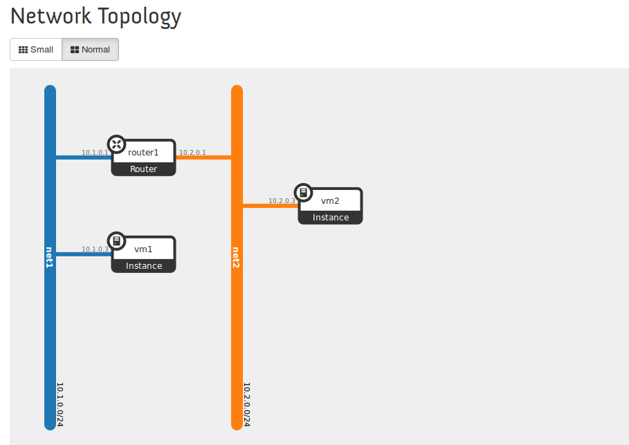
The following diagram shows the OpenStack setup i have configured:
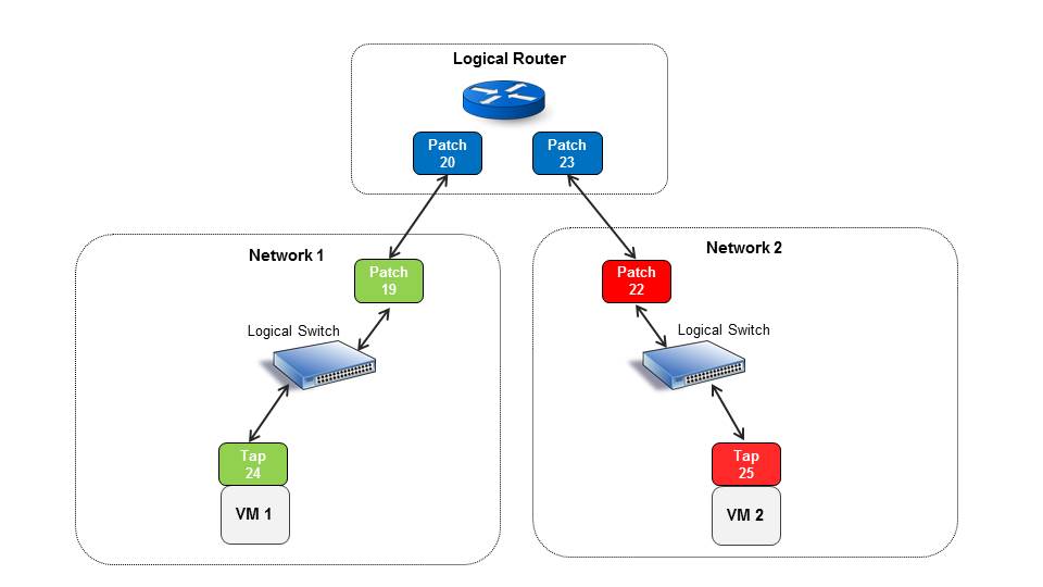
How does OVN implement L3 ? in a nutshell it uses a pair of OVS patch ports to simulate a connection between logical switch (OpenStack network) to logical router (OpenStack router) and in order to do it, it creates a pair of patch ports for every logical router port.
If you are interested in understanding more about patch ports, you can read this post, it describe how patch ports are used to connect two different OVS bridges, in our example they are connected to the same bridge and used as a modeling construct but the concept is the same.
If we print the OVS ports in our bridge we get the following list
OFPST_PORT_DESC reply (xid=0x2):
 1(tapfee83ab5-5f): addr:62:8c:72:4c:26:df
     config:     PORT_DOWN
     state:      LINK_DOWN
     speed: 0 Mbps now, 0 Mbps max
 16(tapdf2a478a-5b): addr:00:00:00:00:00:00
     config:     PORT_DOWN
     state:      LINK_DOWN
     speed: 0 Mbps now, 0 Mbps max
 17(tap071b1892-67): addr:00:00:00:00:00:00
     config:     PORT_DOWN
     state:      LINK_DOWN
     speed: 0 Mbps now, 0 Mbps max
 19(patch-10f594b4-): addr:4e:d2:16:a9:83:17
     config:     0
     state:      0
     speed: 0 Mbps now, 0 Mbps max
 20(patch-5de69aae-): addr:66:a6:a1:a0:12:e6
     config:     0
     state:      0
     speed: 0 Mbps now, 0 Mbps max
 22(patch-d77ee94a-): addr:76:8b:05:66:a3:38
     config:     0
     state:      0
     speed: 0 Mbps now, 0 Mbps max
 23(patch-7581ba34-): addr:fa:b7:bf:7a:9a:8a
     config:     0
     state:      0
     speed: 0 Mbps now, 0 Mbps max
 24(tapaacde712-12): addr:fe:16:3e:a4:d1:b5
     config:     0
     state:      0
     current:    10MB-FD COPPER
     speed: 10 Mbps now, 0 Mbps max
 LOCAL(br-int): addr:c6:75:4f:5e:50:47
     config:     PORT_DOWN
     state:      LINK_DOWN
     speed: 0 Mbps now, 0 Mbps max
What we can see is we have four patch ports and four tap ports, the tap ports are for our two VMs and additional two ports for the DHCP namespaces (OpenStack reference DHCP implementation creates a namespace with dnsmasq per network and since we are in a single node setup we have them all connected to our bridge).
As we can see OVN also created 4 patch ports for the two logical router legs, patch ports are coming in pairs and we can see that patch port 19 and 20 are connected as peers and the same for ports 23 and 24.
For every pair, one port represent the side on the logical switch and another patch port used to represent the logical router side. In order to identify which is which we can check the id in the name.
Following is a partial dump of OVN Northbound DB:
Logical_Router_Port table
_uuid                                enabled external_ids mac                 name                                   network       peer
------------------------------------ ------- ------------ ------------------- -------------------------------------- ------------- ----
5de69aae-545d-4aca-93a7-36685b60fa06 []      {}           "fa:16:3e:6c:c0:33" "10f594b4-a762-4ba0-86fb-a76fe7ad0538" "10.1.0.1/24" []
7581ba34-2926-482c-b95e-5b56e863adb9 []      {}           "fa:16:3e:70:41:c5" "d77ee94a-b57c-48a4-a300-7093f02f49a1" "10.2.0.1/24" []
We can see that the first logical router port name start with 10f594b4, the same as the name of patch port 19. This means that this port is basically the logical switch default gateway and has the IP 10.1.0.1, it is treated as part of that logical switch in the pipeline (as we will soon see).
Its peer port (20) is basically its end point in the logical router side and is later used in the pipeline for the routing process.
The following diagram tries to explain this better:
The Pipeline
Lets now see how this modeling is actually implemented in the OpenFlow pipeline in the local OVS. I will describe the main parts as i see them, its important to note that there are additional parts used for security and RFC compliance that are done in the pipeline and i will not describe them as i dont want to make this too long.
Ports Classification
If we look at the first table we can see how the patch ports are treated
 cookie=0x0, duration=10428.153s, table=0, n_packets=3, n_bytes=987, priority=100,in_port=20 actions=set_field:0x6->metadata,set_field:0x1->reg6,resubmit(,16)
 cookie=0x0, duration=10428.153s, table=0, n_packets=0, n_bytes=0, priority=100,in_port=19 actions=set_field:0x4->metadata,set_field:0x1->reg6,resubmit(,16)
 cookie=0x0, duration=7295.704s, table=0, n_packets=2, n_bytes=658, priority=100,in_port=23 actions=set_field:0x6->metadata,set_field:0x2->reg6,resubmit(,16)
 cookie=0x0, duration=7295.704s, table=0, n_packets=0, n_bytes=0, priority=100,in_port=22 actions=set_field:0x5->metadata,set_field:0x1->reg6,resubmit(,16)
 cookie=0x0, duration=5325.304s, table=0, n_packets=9, n_bytes=1455, priority=100,in_port=24 actions=set_field:0x4->reg5,set_field:0x4->metadata,set_field:0x2->reg6,resubmit(,16)
 cookie=0x0, duration=66.190s, table=0, n_packets=8, n_bytes=1126, priority=100,in_port=25 actions=set_field:0x5->reg5,set_field:0x5->metadata,set_field:0x2->reg6,resubmit(,16)
We can see that patch ports 19 and 22 represent the default gateway ports (IPs 10.1.0.1 and 10.2.0.1) and are classified with metadata numbers that fits their logical switchs (metadata represent the logical switch/network, every local controller allocate running numbers that are unique per logical switch).
We can also see that patch ports 20 and 23 are classified with the same metadata number (6) which represent all the ports attached to the logical router, this is later used for routing.
ARP Responders and Ping
Next in the pipeline we can see that there are ARP responders installed for all the router ports and ping responders (ICMP echo request)
 cookie=0x0, duration=10428.269s, table=17, n_packets=0, n_bytes=0, priority=90,icmp,reg6=0x1,metadata=0x6,nw_dst=10.1.0.1,icmp_type=8,icmp_code=0 actions=move:NXM_OF_IP_SRC[]->NXM_OF_IP_DST[],set_field:10.1.0.1->ip_src,set_field:255->nw_ttl,set_field:0->icmp_type,set_field:0->reg6,set_field:0->in_port,resubmit(,18)

 cookie=0x0, duration=10428.268s, table=17, n_packets=0, n_bytes=0, priority=90,icmp,reg6=0x1,metadata=0x6,nw_dst=10.1.0.255,icmp_type=8,icmp_code=0 actions=move:NXM_OF_IP_SRC[]->NXM_OF_IP_DST[],set_field:10.1.0.1->ip_src,set_field:255->nw_ttl,set_field:0->icmp_type,set_field:0->reg6,set_field:0->in_port,resubmit(,18)

 cookie=0x0, duration=7295.816s, table=17, n_packets=0, n_bytes=0, priority=90,icmp,reg6=0x2,metadata=0x6,nw_dst=10.2.0.1,icmp_type=8,icmp_code=0 actions=move:NXM_OF_IP_SRC[]->NXM_OF_IP_DST[],set_field:10.2.0.1->ip_src,set_field:255->nw_ttl,set_field:0->icmp_type,set_field:0->reg6,set_field:0->in_port,resubmit(,18)

 cookie=0x0, duration=7295.816s, table=17, n_packets=0, n_bytes=0, priority=90,icmp,reg6=0x2,metadata=0x6,nw_dst=10.2.0.255,icmp_type=8,icmp_code=0 actions=move:NXM_OF_IP_SRC[]->NXM_OF_IP_DST[],set_field:10.2.0.1->ip_src,set_field:255->nw_ttl,set_field:0->icmp_type,set_field:0->reg6,set_field:0->in_port,resubmit(,18)

 cookie=0x0, duration=10428.268s, table=17, n_packets=0, n_bytes=0, priority=90,arp,reg6=0x1,metadata=0x6,arp_tpa=10.1.0.1,arp_op=1 actions=move:NXM_OF_ETH_SRC[]->NXM_OF_ETH_DST[],set_field:fa:16:3e:6c:c0:33->eth_src,set_field:2->arp_op,move:NXM_NX_ARP_SHA[]->NXM_NX_ARP_THA[],set_field:fa:16:3e:6c:c0:33->arp_sha,move:NXM_OF_ARP_SPA[]->NXM_OF_ARP_TPA[],set_field:10.1.0.1->arp_spa,set_field:0x1->reg7,set_field:0->reg6,set_field:0->in_port,resubmit(,32)

 cookie=0x0, duration=7295.816s, table=17, n_packets=0, n_bytes=0, priority=90,arp,reg6=0x2,metadata=0x6,arp_tpa=10.2.0.1,arp_op=1 actions=move:NXM_OF_ETH_SRC[]->NXM_OF_ETH_DST[],set_field:fa:16:3e:70:41:c5->eth_src,set_field:2->arp_op,move:NXM_NX_ARP_SHA[]->NXM_NX_ARP_THA[],set_field:fa:16:3e:70:41:c5->arp_sha,move:NXM_OF_ARP_SPA[]->NXM_OF_ARP_TPA[],set_field:10.2.0.1->arp_spa,set_field:0x2->reg7,set_field:0->reg6,set_field:0->in_port,resubmit(,32)
These are in charge of replying to ARP or pings on the default gateway for each logical switch (the router ports, IPs 10.1.0.1 and 10.2.0.1)
Routing and Destination Lookup
In this section we are going to see the interesting part of how distributed routing is done. Following are the steps when VM1 tries to reach VM2 in our setup:
1) VM1 tries to find its default gateway MAC address by sending an ARP request for 10.1.0.1
2) The ARP responder mentioned above create and sends a reply (all done in flows) and sends patch port 19 MAC address.
3) VM1 sends packet with patch port 19 MAC address, which is going the same route as any other L2 traffic and in the end (egress table) sent to this port.
4) Since patch port 20 is a peer of patch port 19 the traffic re-enters the pipeline on table 0, but the in-port is now port 20, its being classified and tagged with metadata=6
5) Then comes the interesting part in table 18 and 19:
 cookie=0x0, duration=10428.268s, table=18, n_packets=0, n_bytes=0, priority=24,ip,metadata=0x6,nw_dst=10.1.0.0/24 actions=dec_ttl(),move:NXM_OF_IP_DST[]->NXM_NX_REG0[],resubmit(,19)

 cookie=0x0, duration=7295.816s, table=18, n_packets=0, n_bytes=0, priority=24,ip,metadata=0x6,nw_dst=10.2.0.0/24 actions=dec_ttl(),move:NXM_OF_IP_DST[]->NXM_NX_REG0[],resubmit(,19)
We can see that what we do is match on metadata (which is 6 for indicating all the router ports group) and on the subnet destination. Since the destination is VM2 (IP 10.2.0.3) the second flow is matched and packet is sent to table 19, we also set the final destination IP in reg0 and we will soon see why.
We can also see that we decrement the TTL (similar to what a router would do at this point).
If we look at table 19 we can see the following flows:
 cookie=0x0, duration=10428.162s, table=19, n_packets=0, n_bytes=0, priority=200,reg0=0xa010001,metadata=0x6 actions=set_field:fa:16:3e:6c:c0:33->eth_src,set_field:fa:16:3e:6c:c0:33->eth_dst,set_field:0x1->reg7,resubmit(,32)

 cookie=0x0, duration=7295.710s, table=19, n_packets=0, n_bytes=0, priority=200,reg0=0xa020001,metadata=0x6 actions=set_field:fa:16:3e:70:41:c5->eth_src,set_field:fa:16:3e:70:41:c5->eth_dst,set_field:0x2->reg7,resubmit(,32)

 cookie=0x0, duration=5326.167s, table=19, n_packets=0, n_bytes=0, priority=200,reg0=0xa010003,metadata=0x6 actions=set_field:fa:16:3e:6c:c0:33->eth_src,set_field:fa:16:3e:a4:d1:b5->eth_dst,set_field:0x1->reg7,resubmit(,32)

 cookie=0x0, duration=67.313s, table=19, n_packets=0, n_bytes=0, priority=200,reg0=0xa020003,metadata=0x6 actions=set_field:fa:16:3e:70:41:c5->eth_src,set_field:fa:16:3e:fe:37:f2->eth_dst,set_field:0x2->reg7,resubmit(,32)
As we can see we have a match on reg0 and the metadata, reg0 holds all the possible IPs that the router could reach, we can see here the router ports IPs (10.1.0.1, 10.2.0.1) and our both VMs IPs (10.1.0.3 and 10.2.0.3). In our case the last flow is matched (destination IP is 10.2.0.3 for VM2).
We can also see that we switch the MAC addresses of the source and destination depending on the destination VM MAC and the router port MAC address (again similar to what a router would do)
The following diagram depicts OVS in this setup:
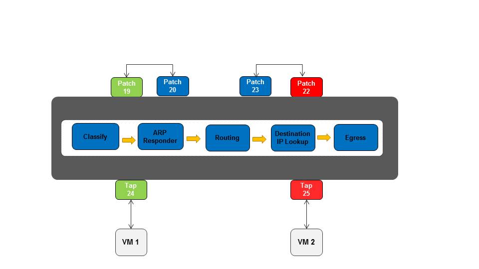
The following steps summarize the routing process in OVN:
1) The idea is that when a VM try to communicate with another subnet (L3), OVN first sends the traffic to the patch port which represent the default gateway for the VM subnet.
2) Then the packet re-enter the pipeline with an in-port that represent the router side (the patch port peer) and being classified with the same metadata group number.
3) Routing happens, there are matching flows for all the possible destination subnets this packet can reach (depending on the router ports).
4) After OVN identified that the destination is routable the next step is to identify the exact destination according to the destination IP (which is now in reg0 as a hex value).
5) Replace the MAC addresses according to the destination and the router port and send to the final destination.
Its important to note that patch ports traffic traversing should have relatively light performance impact as they are only simulated in the user space OF pipeline process. When the kernel flows are installed the patch ports shouldn’t exists, which makes them more of a modeling construct than a real port in the system.
I hope this posts gave you a high level insight of how distributed L3 is implemented in OVN, there are many little details which weren’t mentioned and i hope to cover them in future posts. (like how all this is combined with security and connection tracking and so on).
Tags: NFV · Neutron · OVN · OVS · Openstack ← Previous Post: Topology Service Injection Next Post: Dragonflow Security Groups At Scale →